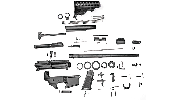
When I was a kid, about a million years ago, I loved to build things. Legos were my prime construction materials as a little boy. Never outgrowing the fascination with building things, and not having reached adulthood yet, I discovered that the AR rifle is easily the most accessorize-able firearm in the world.
- RELATED STORY: DIY: 13 Steps For Building the Perfect Custom 6.5 Match King
With more unique, user-friendly, customizable parts than any other, I had found my “big boy” Legos. With minimum tools, a modicum of basic mechanical skill and an understanding of the rifle’s operation, most anyone can build their own personalized AR, all while saving an additional 11 percent on the purchase since it is exempt from federal excise tax. And you can build it your way.
Starting Point
Advertisement — Continue Reading Below
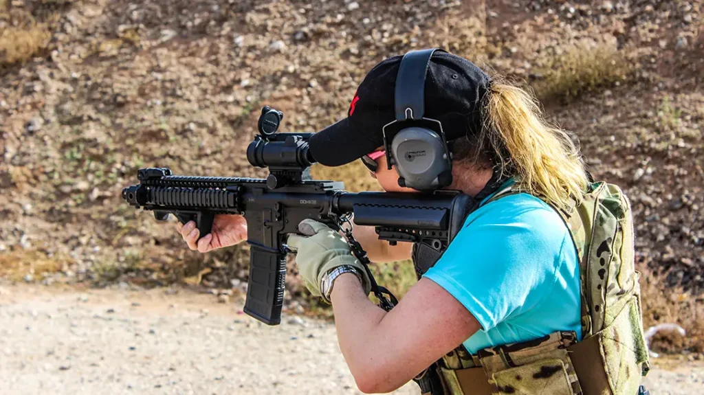
For this build, I selected a DPMS lower receiver and an Oracle Rifle Kit as my foundation, based on my experience with the company’s quality and reliability. I also appreciate that the Oracle kit has a bolt factory-headspaced to the barrel as well as several subassemblies completed by DPMS, guaranteeing correct assembly of those parts and shortening the build time. An Ace SOCOM stock, a free-floating GunTec USA KeyMod forend and an Ergo grip rounded out my personal choices for this build, but the assembly instructions here are predominately the same for similar products. For liability and reliability reasons, I recommend that the barrel installation, bolt headspacing and gas block/front sight installation be completed by a qualified gunsmith. However, the bulk of a basic AR build is a DIY dream.
Tools Required
- Safety glasses
- 1/16” punch
- 3/32” punch
- 1/8” punch
- 1/4” punch
- CAR stock wrench and/or AR-15 multi-tool
- Small hammer
- Flat-bladed or slotted screwdriver
- Lower receiver block
- Upper receiver block
- Delrin gunsmithing block or small block of wood
- Bench vise
- Optional: Roll pin starting and finishing punches. These make the job much easier and reduce the likelihood of marring the finish or damaging pins.
To simplify assembly, separate the upper and lower receiver parts into groups and build one half at a time, noting that some assembly must be completed in a specific order, such as the fire control group or bolt carrier group. After completing installation of each individual part, confirm it functions correctly through its range of motion before moving forward in order to prevent disassembly to correct an error later.
Advertisement — Continue Reading Below
Lower Receiver
Begin by placing the lower receiver on the lower receiver block that you have secured in a bench vise. Then put on your your safety glasses. You already know where these go.
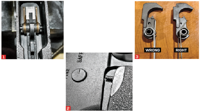
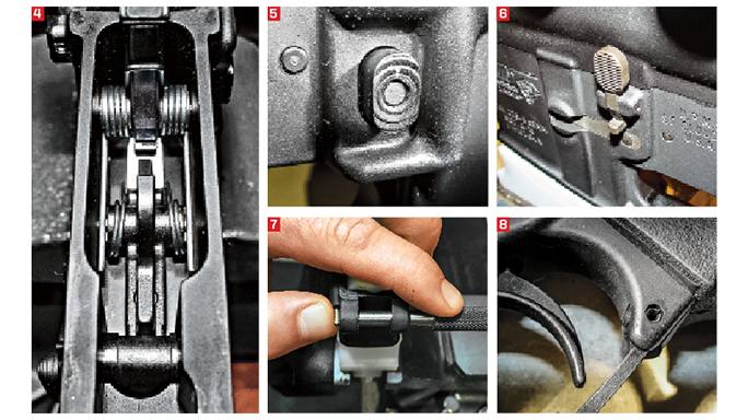
- Installing The Trigger: Begin assembly of the fire control group by installing the trigger spring onto the trigger. Push each set of coils over the corresponding side of the trigger at the trigger pinhole location, with the legs pointing forward and the square portion of the spring applying pressure to the forward, underside of the trigger. Once complete, insert the large coil of the disconnector spring into the trigger housing by pushing straight down while twisting clockwise until it seats and is held captive. When seated, the disconnector can be placed loosely in position, with the spring applying pressure inside the square cut located behind the trigger pinhole. Place the entire assembly into the lower receiver and align it with a punch to hold the parts captive. Insert the trigger pin from the opposite side and guide it through the lower, trigger housing and disconnector to the opposite side of the lower receiver as you push the punch free. Function-test the trigger to confirm it resets by pulling the trigger normally and releasing it. The trigger should automatically return to its forward position.
- Safety Selector: Remove the lower from the block for this assembly. Place the safety selector through the left side of the lower receiver with the selector lever correctly positioned between the “safe” and “fire” stops. Turning the lower receiver upside down, insert the safety selector detent, pointed-end first, into the raceway in the lower receiver. Place the pistol grip screw and locking washer through the hole in the pistol grip and start the grip onto the lower receiver. Once the pistol grip screw is started, insert the safety selector detent spring into the pistol grip and align it with the corresponding raceway holding the detent. When correctly aligned, push the pistol grip flush onto the lower and tighten the pistol grip screw until snug, plus a quarter or half turn.
- Hammer Spring: The hammer spring is held captive by the coils that encircle each side of the hammer where the hammer pinhole is located. To install, slip one section of the coils across the hammer pinhole, orienting the square portion of the spring to apply pressure to the rear of the hammer and snap the opposite coils over the opposing hammer pinhole. (Note: The coils compress through the normal range of motion when the hammer spring is installed correctly. It is possible to reverse this installation, placing the hammer spring on backwards, thus opening the coils of the spring. This condition will pass a basic function check. However, it often results in light primer strikes.)
- Hammer Installation: Place the lower back on the receiver block. To install the hammer, place the legs of the hammer spring on the outside of each side of the trigger housing, on top of the trigger pin. Depress the hammer into the lower receiver until the hammer pinhole aligns properly with the corresponding holes in the lower receiver so it can be held captive with a punch. Push the hammer pin through lower from the opposite direction while removing the punch. Proper alignment of the hammer within the lower receiver will normally allow the hammer pin to be easily installed without the use of tools, but a slight tap with a small hammer may be required to force the hammer pin past the “J” spring (located in the center of the hammer itself to retain the hammer pin) during installation.
- Magazine Release: Begin by placing the magazine release spring into the right side of the lower receiver. Place the magazine release button, serrated-side out, on top of the spring and depress it below the surface of the lower receiver. Insert the magazine release from the left side of the receiver and turn it clockwise until the stem (threaded portion) of the magazine release is flush or level with the surface of the magazine release button, or one compete turn below flush. The stem of the magazine release should never protrude from the button.
- Bolt Release: Start the bolt release roll pin using a 3/32” punch or 3/32” Roll Pin Starter Punch. Once started, but not projecting into the opening for the bolt release, insert the bolt release spring, bolt release detent and the bolt release into the raceway of the lower receiver using a punch to hold the parts captive. Once aligned correctly, drive the roll pin through the bolt release and seat it slightly below the surface of the receiver, evenly on both sides. (Duct or masking tape applied to this receiver area prior to installation will help protect the finish from marring).
- Pivot Pin: There are several methods of installing the pivot pin. Most use specialized tools to hold the detent and spring captive. The following method can be used effectively without specialized tools. Insert a ¼” punch through the pivot pinholes in the lower from the left side. Place the pivot pin detent spring in the raceway. Balance the pivot pin detent on top of the spring and pinch it between your thumb and the punch face. Use the end of the pivot pin to depress the detent flush within the raceway and then turn the pivot pin 90 degrees into the pivot pinhole, forcing the punch out. Rotate the pivot pin in either direction to allow the detent to engage the pivot pin raceway.
- Triggerguard: Remove the lower from the block. After supporting the triggerguard housing using wood or a polymer gunsmithing block to support the “wings” of the trigger housing, install the triggerguard by allowing the detent to lock the forward portion in place, align the rear triggerguard hole with the hole in the trigger housing and start the roll pin using a punch. Carefully drive the roll pin through the triggerguard and seat it flush once it enters the triggerguard pinhole in the opposite “wing” of the triggerguard housing. (Note: If significant resistance is encountered, do not force the roll pin, as damage to the lower receiver may result, most commonly breaking one of the “wings” from the triggerguard housing. This is not a defect in workmanship and is not a warranty repair or replacement.)
Installing A Collapsible Stock
Advertisement — Continue Reading Below
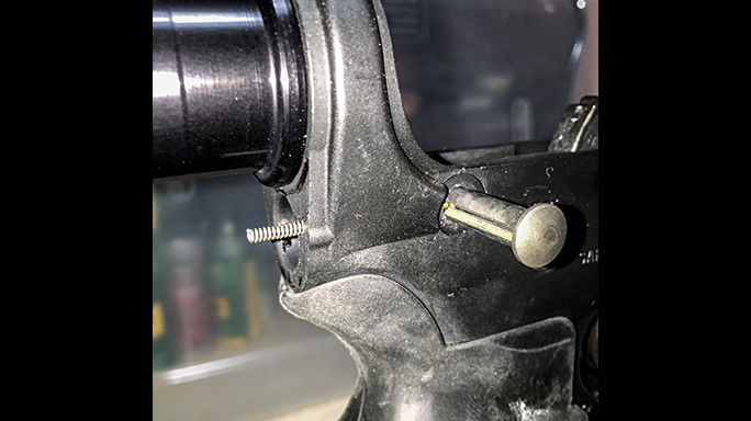
- When installing a collapsible stock, be cautious when indexing the lower receiver extension (aka buffer tube) to ensure no damage occurs to the takedown detent spring and that the extension is indexed enough to hold the buffer retainer without protruding into the lower receiver and preventing the upper from closing on the lower.
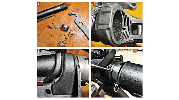
- First, place the lower back on the block and install the takedown pin from right to left through the lower receiver. Do not worry about indexing it in the raceway for the detent at this time. Insert the takedown detent into the corresponding hole in the lower receiver. Note: Do not install the takedown detent spring at this point. Install the buffer retainer spring and buffer retainer into the corresponding hole in the 6 o’clock position of the threaded portion of the lower receiver. Install the castle nut, with the engagement lugs pointed rearward, on the lower receiver extension, and screw it all the way to the back of the threaded portion of the lower receiver extension. Install the latch plate with the indexing lug sliding freely in the raceway on the bottom of the lower receiver extension and push it to the rear of the threads against the castle nut. Carefully begin threading the lower receiver extension into the lower receiver by turning it clockwise. As the lower receiver extension approaches the buffer detent and buffer detent spring location, depress the detent below the plane of the lower receiver extension to allow it to engage and retain the buffer retainer once correctly indexed. The lower receiver extension should protrude just enough for approximately one-third of the buffer retainer to be covered by the lower receiver extension. (Note: Do not force the extension against the buffer retainer, as this will split or shatter the lower receiver wall just forward of the buffer retainer hole. If the lower receiver extension is over-indexed, the buffer retainer will not retain the buffer and/or the upper receiver will not close on the lower. If the lower receiver extension is under-indexed, the buffer retainer will not be held captive and will release into the bolt carrier group when the rifle is cycled manually or by firing.) Once the lower receiver is correctly indexed, confirm the rear takedown pin is still in place and insert the takedown pin detent spring into the corresponding hole in the lower receiver. Carefully slide the latch plate forward, compressing the takedown pin detent spring, and tighten the castle nut snugly using your fingers.
- Rotate the rear takedown pin within the lower receiver in order to engage the detent in the raceway, allowing it to be retained within the lower receiver. Using a lower receiver block that firmly locks the lower into a bench vise, use a torque wrench or the collapsible stock wrench to tighten the castle nut to 38 to 42 inch-pounds. If you lack a torque wrench, this is approximately a quarter to half turn after making certain it is correctly indexed in the 12 to 6 o’clock position. Install the buffer spring, then the buffer, and confirm they are held captive through normal range of motion.
- Staking The Castle Nut: Staking is using an appropriate staking punch to expand a small portion of steel from the latch plate into the corresponding recess on the backside of the castle nut. A staking punch “rolls” or “pushes” material from one part into another after several firm strikes of a hammer. Locate a recess (there are three spread equidistant around the base of the castle nut) and seat a staking punch (or substitute a 3/32” punch) on the latch plate next to the recess, slightly angled towards the recess itself. Strike the head of the punch to expand the latch plate material into the recess. Repeat as necessary until a small portion of the material expands into the recess to lock the castle nut. As an option to staking, a locking agent can be applied to the threads prior to torqueing.
Installing The Stock: Pull the collapsible stock’s latch straight down, away from the stock body, and install it on the lower receiver extension. When releasing the stock latch, it should be held captive throughout its range of motion.
Installing A Fixed Stock
First, install the buffer retainer spring and buffer retainer into the corresponding hole in the 6 o’clock position of the threaded portion of the lower receiver. Carefully begin threading the lower receiver extension into the lower receiver by turning clockwise. As the lower receiver extension approaches the buffer detent and buffer detent spring location, depress the detent below the plane of the lower receiver extension to allow it to engage and retain the buffer retainer once correctly indexed. In this case, the lower receiver extension’s shoulder will “bottom out” against the lower receiver.
Advertisement — Continue Reading Below
Next, install the takedown pin from right to left through the lower receiver. Do not worry about indexing the raceway for the detent at this time. Insert the takedown detent, then the takedown detent spring, into the corresponding hole in the lower receiver. Insert the A2 stock extension, with the threaded portion for the stock screw first, into the A2 stock slot that accepts the lower receiver extension. Slide the A2 buttstock onto the lower receiver extension carefully, paying particular attention to the takedown detent spring, ensuring it is not deformed when the stock is seated against the lower receiver. Install the stock screw clockwise until snug and then give it a quarter to half turn to secure it.
Upper Receiver
For this DIY build, the barrel and gas block (or front A-frame sight assembly) should be installed and headspaced by a qualified gunsmith. This would include the barrel nut, delta pack and handguard cap for two-piece handguards and/or the installation of a free-floating forend, including the gas tube.
Advertisement — Continue Reading Below
For the upper assembly, I prefer the DPMS Panther Claw upper receiver block, or similar, to allow work to be completed without the upper receiver being completely shrouded by a “pancake type” block, but you can work without a block for some assembly, if necessary.
Charging Handle Latch: Using a punch, start the roll pin into the latch without allowing it to protrude into the slot for the latch. Insert the charging handle latch spring into the slot and then align the charging handle latch with the pinhole using a punch. Once properly aligned, drive the roll pin through the latch and the opposite side of the charging handle, leaving it flush on both sides.
- Forward Assist: With the upper assembly mounted on the receiver block, place the forward assist spring on the forward assist, over the forward portion or pawl. Start the forward assist roll pin in the corresponding hole in the top of the upper receiver without allowing it to protrude into the raceway for the forward assist. Insert the forward assist assembly into the raceway with the pawl oriented to engage the serrations on the bolt carrier and depress slightly to allow the roll pin to pass through the recess cut into the forward assist. Once properly oriented and aligned, drive the roll pin past the forward assist and flush with the surface of the upper receiver. There should be no significant resistance when installing the forward assist roll pin. If significant resistance is encountered, the forward assist is misaligned, installed backwards or not compressed enough to allow the pin to pass through the recess cut. Damage to the forward assist may result from incorrect alignment.
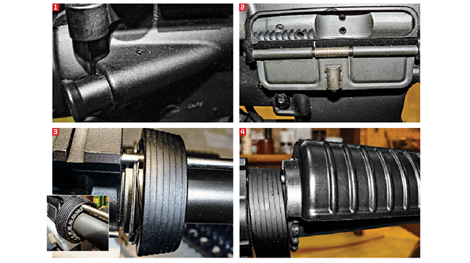
- Dust Cover: To install the dust cover, insert the dust cover pin into the rear lug, then through the dust cover until it protrudes approximately a quarter-inch into the opening for the dust cover spring. Attach the dust cover spring to the dust cover pin, short-leg-side first, with the short leg of the spring pointing up and resting against the upper receiver. Grasp the long leg of the spring and pull it away from the receiver, keeping the short leg firmly against the upper receiver, and twist it one full turn clockwise before seating the long leg in the corresponding recess of the dust cover. This “loads” the spring to provide the tension necessary to open the dustcover. Once in place, push the dust cover pin through the remainder of the spring and dust cover, and then through the forward lug. Before installing the “C” clip, function-test the door to be certain it is working properly. Press the “C” clip into place using pliers or tweezers, finishing with a large punch to seat as necessary.
- Gas Tube: Insert the gas tube, “mushroomed” end first, through the delta pack and into the upper receiver. The holes in three components of the delta pack (delta ring, weld spring and barrel snap ring) may have to be aligned in order to insert the gas tube into the upper. Use a punch to rotate each part accordingly. Once inserted into the upper receiver enough to clear the sight housing/gas block, rotate the gas tube so the port opening is oriented down towards the barrel. The offset in the gas tube should run downhill from the upper receiver to the sight housing/gas block. Align the roll-pin hole in the gas tube with the roll-pin hole in the sight tower/gas block and install the roll pin. Once installed, make certain the roll pin holds the gas tube in place by pulling forcefully on the gas tube, back towards the receiver. Note: Installation of a gas tube within a free-floating forend must be completed when the gunsmith installs the gas block and free-floating forend.
- CAR Or A2 Handguards: Insert the small end of the handguard into the handguard cap, with the top half of the handguards first. Compress the delta pack until the base of the handguard slips over the face of the delta ring. Before seating the handguard into the barrel nut, allow it to “hold” one half of the delta pack in the compressed position. This allows leverage to assist in compressing the other half of the delta pack to install the lower half of the handguards. Once both are past the delta ring, release the delta ring, allowing it to retain the handguards. A slight tap on the delta ring may be required to seat the handguards once installed.
- A2 Front Sight Post: Insert the front sight detent spring into the detent raceway located forward of the threaded section of the front sight housing. Place the front sight detent on top of the spring. Depress with a punch and thread the front sight into place, indexing the front sight post’s base flush with the front sight post housing.
- Flash Suppressor: With the entire upper receiver assembly in the upper receiver block as noted above, install the crush washer with the smaller of the two “beveled” sides, the convex side, against the barrel. Thread the flash suppressor on, turning clockwise, until snug on the larger bevel, or concave side, of the crush washer. At this time, the five slots of the A2-style flash suppressor need indexing to center the third slot on the front sight post. For aftermarket flash suppressors, use the manufacturer’s instructions on indexing correctly. Place a Multi-Tool on the “flats” of the flash suppressor and turn clockwise until correctly indexed.
- Bolt Carrier Group: The bolt carrier group consists of five parts: the carrier (with key installed), the bolt (with gas rings, ejector and extractor installed), firing pin, cam pin and firing-pin retaining pin. Begin by inserting the bolt into the bolt carrier with the extractor facing the 10 o’clock position when viewing the bolt face. Insert the cam pin through the carrier and the bolt and rotate 90 degrees. Pull the bolt to the open position and insert the firing pin from the rear of the carrier through the bolt. Install the firing pin retaining pin through the carrier from right to left when looking at the bolt. Install the charging handle at approximately a 30-degree downward angle into the upper receiver, leaving enough clearance to insert the carrier key into the charging handle, and push the entire assembly closed until it latches.
Now you are ready to install the upper assembly on the lower and complete a basic function check.
Advertisement — Continue Reading Below
Basic Function Check
With the safety selector in the “safe” position, clear the weapon and make it safe by removing the magazine, pulling the charging handle all the way to the rear and locking the bolt carrier assembly in place with the bolt catch. Visually and physically inspect the chamber to make certain it is empty. Repeat as necessary to ensure the rifle is not loaded before proceeding. Once the chamber is confirmed to be empty, you may proceed to the next step.
Close the bolt by depressing the bolt catch. With the safety selector in the “safe” position, point the unloaded weapon in a safe direction and pull the trigger. Nothing should happen. Moving the safety selector to the “fire” position and pointing the unloaded weapon in a safe direction, pull the trigger but do not release it. The hammer should fall with an audible click. Without releasing the trigger, grasp the charging handle and re-cock the hammer, simulating the firing of a cartridge during the normal cycle of operation. Release the charging handle to close the bolt. Release the trigger. You should hear an audible click as the disconnector (the secondary sear engagement point) releases the hammer to the primary sear engagement point, the nose of the trigger. Return the safety selector to the “safe” position. This completes the basic function check.
Advertisement — Continue Reading Below
- RELATED STORY: DIY: 15 Steps to Successfully Build Your Own 6.8 SPC
If you have verified the correct function of each individual part during assembly, and the complete rifle passes the basic function check, your DIY rifle is now ready for range time, the goal of your DIY experience.
Ultimately, the fantastic thing about the AR is its user-friendly customization. With basic tools and mechanical skill set, anyone can build a reliable and unique AR using an almost unlimited choice of parts.
For More Information
Advertisement — Continue Reading Below
ACE LTD.: riflestocks.com; 888-736-7725
DPMS: dpmsinc.com; 800-578-3767
GunTec USA: guntecusa.com; 480-478-4517
ERGO Grips: ergogrips.net; 877-281-3783
